
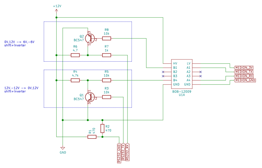
Errata: The schematics of the level shifter had labels switched around: MEDION_3V and MEDION_GND were switched around. This is fixed now since 2022-01-27.
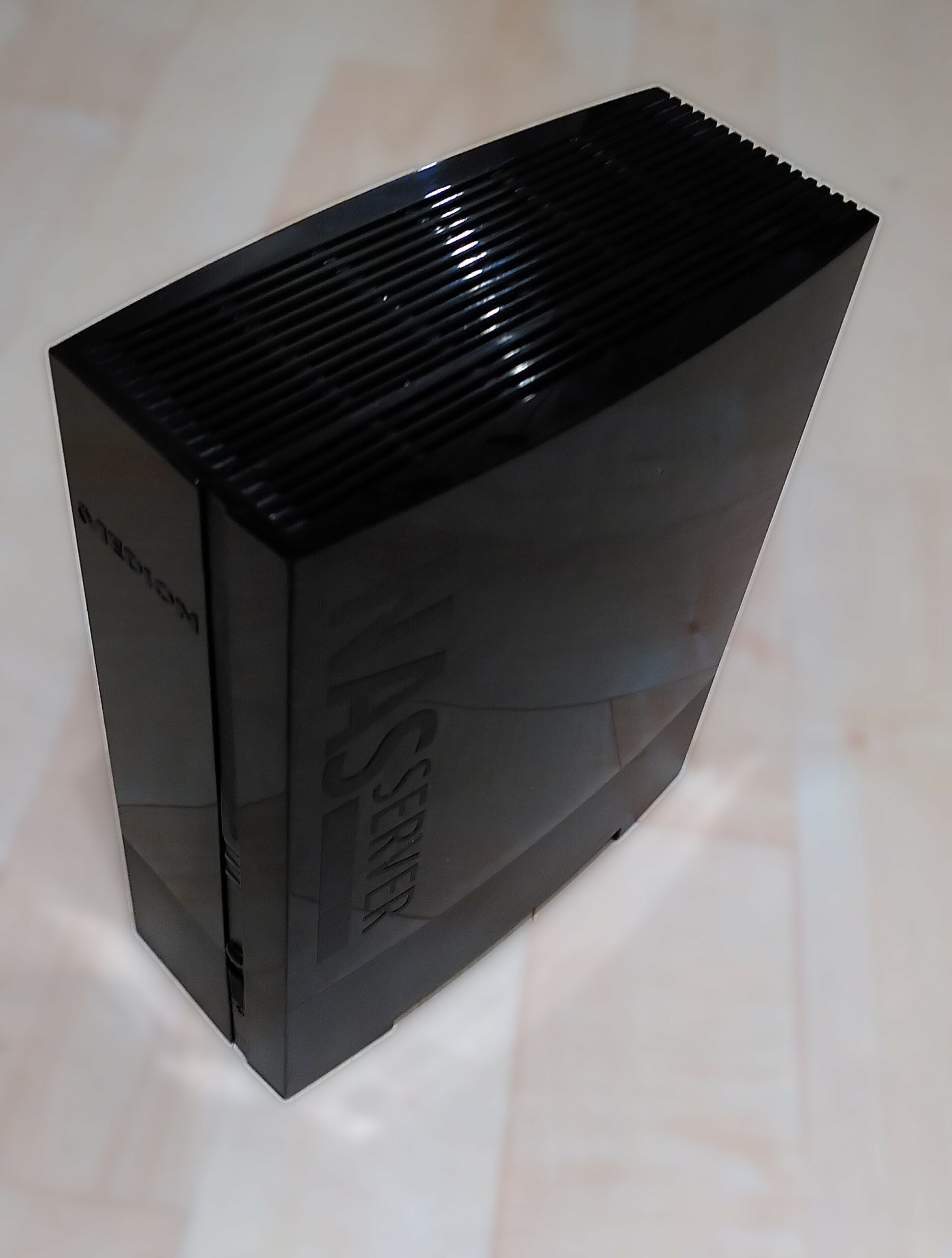
This old Medion NAS comes with an old version of linux with an outdated and insecure version of Samba. The goal of this project is to install an updated version of OpenWrt to revive this product.
Installing OpenWrt on a Medion P89635 NAS server is not trivial. It requires disassembly of the device and interfacing with the on-board system using a serial protocol connected to a debug header on the NAS mainboard. While not being the hardest task, I made some mistakes myself, but ultimately succeeded. If you are comfortable at dealing with electronic circuits you might want to implement another solution for the serial interface.
In this document, I will give step-by-step instructions how I installed OpenWrt on the NAS server. The steps mostly follow the instructions from trailblazer “hondabeat” at this forum entry. I use a Linux host to install OpenWrt so if you use Windows or Mac, this might be of limited use to you. Follow at your own risk.
Device disassembly
This probably is the most exciting bit. The pictures provided are actually taken from the re-assembly. I was not sure what I was doing during disassembly, so this yielded better pictures, but they still were pretty average. So this part might be a bit lacking.
For the installation processes of the Medion NAS, the OpenWrt wiki links to the installation process for a “pogoplug” which seemingly uses an integrated power supply on the mainboard which can make things dangerous. Do not be discouraged, the Medion NAS uses an external 12V powerplug which steps down the voltage safely. You can take it apart and lay it on your table to install it – no high voltages to be found on that board.
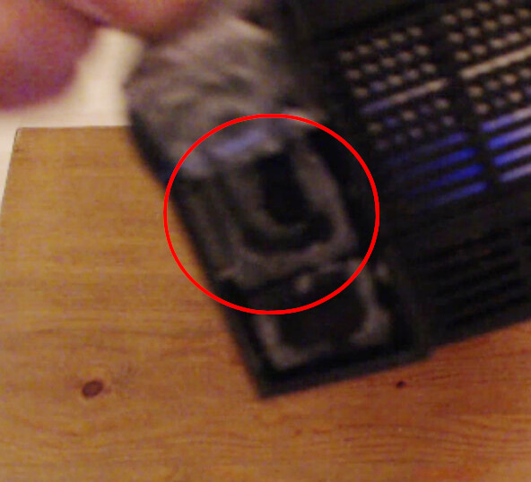
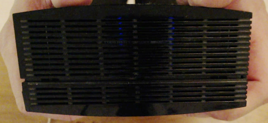
The first step of the disassembly is to carefully pry off the rubber feet. Underneath you will find a single screw per foot.
After unscrewing the two screws under the rubber feet, you are ready to prey apart the plastic shell. The plastic shell is clipped together with some pretty stiff clips.
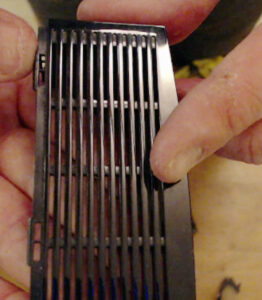
I succeeded by starting at the top of the device and starting to separate the housing from there. I just carefully pried them apart as there was no give in the housing to lever anything. It did not damage my clips.
After unclipping the plastic shell, one half of the shell will come off and reveal a metal housing inside.
Before continuing to remove the remainder of the plastic shell, this is a good time to remove the little rubber-cover for the front USB port before it gets lost.
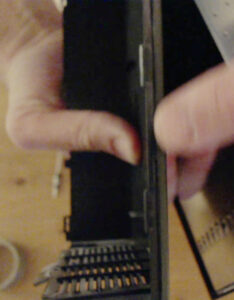
Now it is time to remove the two screws that hold the metal housing inside of the plastic shell. Unscrew the screws and carefully remove the housing. This is a little bit tricky because it contains all the cutouts for the I/O ports.
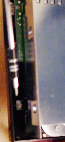
Now, after the plastic shell was removed, it is time to disassemble the inner metal housing and remove the harddrive. The harddrive is not needed to install OpenWrt.
The Metal housing-top cover is held in place by a series of clips. Use a tool to unhinge those clips.
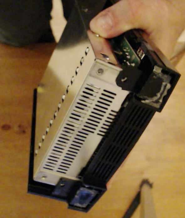
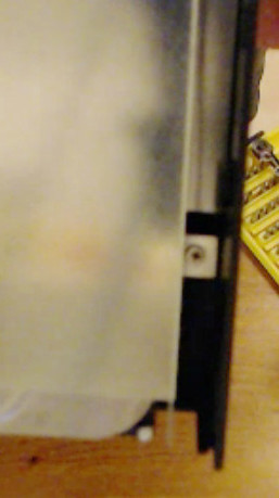
Removing the top-plate will reveal the harddisk for the first time. It is not time to remove that one yet however, because it is still held in place by a set of screws on the underside of the device. The next step is to remove the IO shield on the side of the device. There is a bit of conductive tape that holds the IO shield in place.
Gently, pry back the conductive tape. This will loosen the entire IO shield so that you can pull it off. (Little warning: Getting it on again later is pretty tricky).
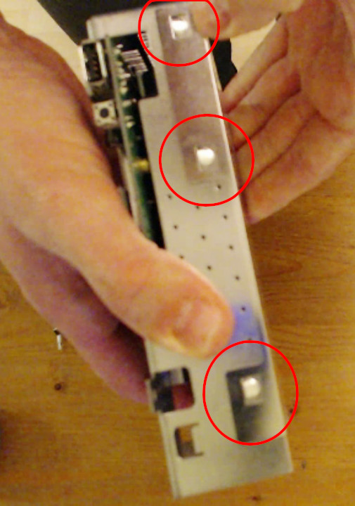
Now it is finally, time to remove the heavy harddisk. There are three screws at the bottom-side of the harddisk that need to be removed. Be careful, because the harddisk is heavy in comparison to the remainder of the hardware and will drop out of the metal shell when not held.
After removing these screws, you can slide out the harddrive. Pull it up slightly to disconnect the SATA connector at the bottom and carefully place it to the side.
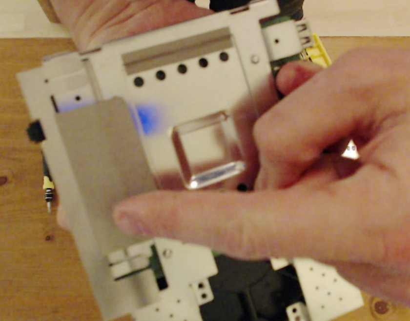
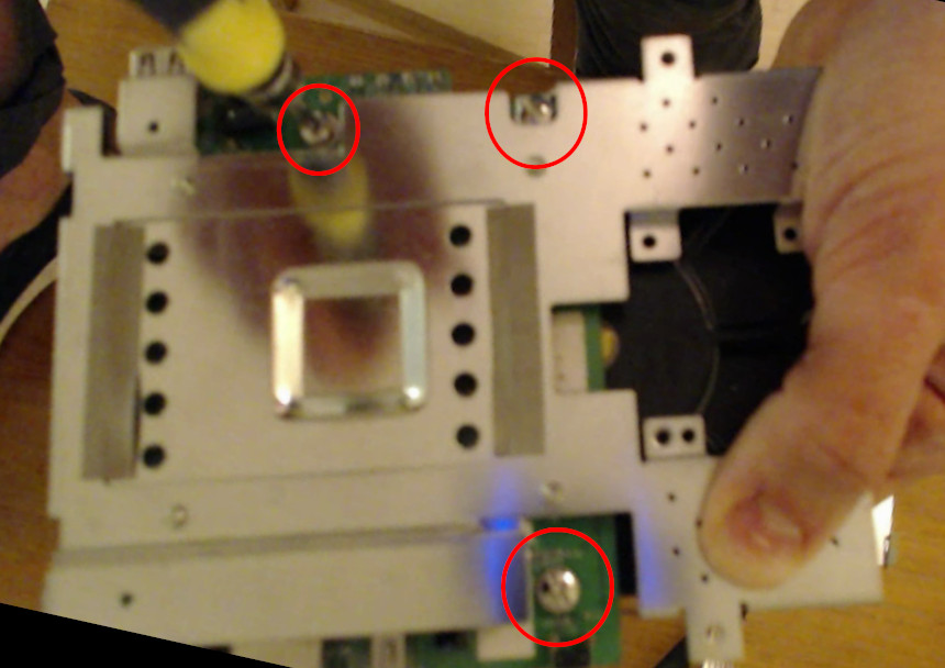
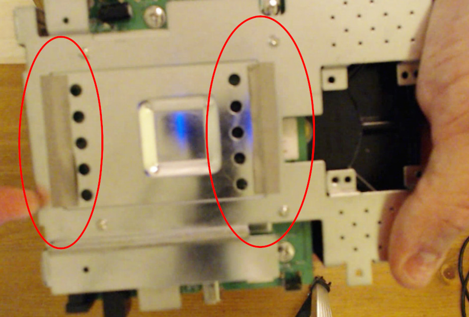
The next step is to remove the bottom cover. First, start by removing the two narrow conductive tapes that connect to the CPU heatsink.
The very last step of the disassembly is to flip the board around and remove four screws from the mainboard to remove the bottom metal shell.
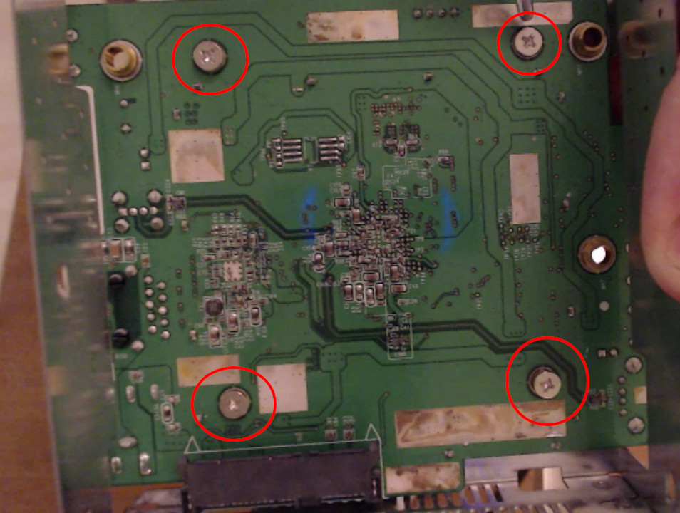
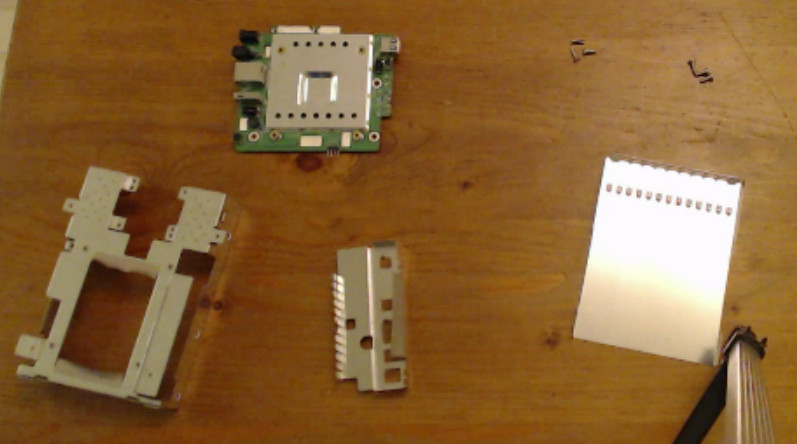
After you removed the four screws, the board can be carefully lifted out of the shell. It needs to be slightly angled up get the IO ports out of the shell. After removing the shell, you hold the mainboard in your hands. That is all you need for the next steps until reassembly.
Interface circuit
The official instructions on the OpenWrt Wiki mention the use of the PL2303HX for connecting your PC to the Medion-NAS. I do not have that device. It is likely easier to do it that way, so do it that way! You can skip the next section in that case, except for the pinout-image.
My custom RS232 level converter
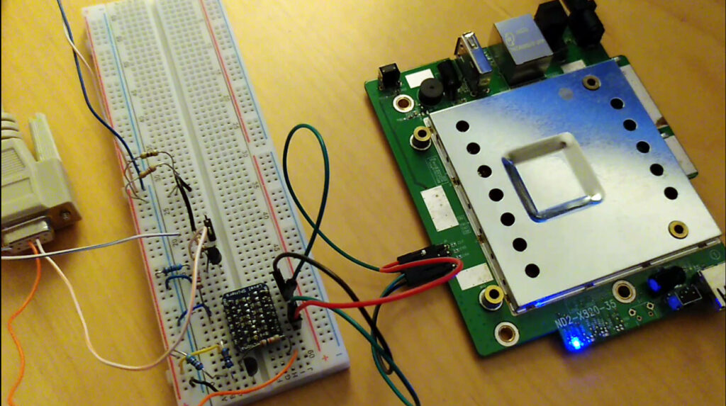
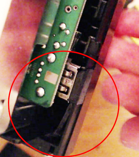
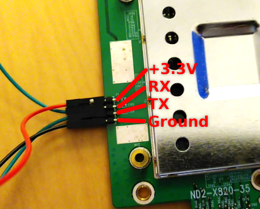
The mainboard has a 4-pin connector on its side. The 4-pin is a serial interface and acts as the screen and keyboard for the device to get access to the bootloader. The 4-pin connector signal is a serial 3.3V interface. I identified the pin labels as follows:
I wanted to be able to install the machine from my PC, so I had to build an interface of some sorts to communicate with it. I chose to use one of my USB-to-RS232 adapters for this. Converting a 0V=low, +3.3V=high signal to RS232 (+12V=low -12V=high) is not super trivial, however. Alternatively, I considered using an Arduino and forwarding the signal from there which might have been easier? It certainly would have been an option.
Anyway, I chose to use the RS232 USB device. So I had to create a circuit that does convert logic levels and inverts the serial signal. I built up that circuit using jumper wires on a proto- board. The schematics of the circuit are shown here:
The circuit requires an external 12V power source for generating the +6/-6V signals I used to feed the RS232 signal. Resistors R1 and R2 (bottom) leak a lot of current to generate a +6V reference to GND which is used as RS232_GND. There is one core component used in this board which is a level shifter built like the Sparkfun BOB-12009 (I will not say “clone” here as this board implements a rather simple and standard MOSFET-based levelshifter). It might not have been necessary, but this circuit generally is rater quick-and-dirty than sophisticated.
There is a definitive small warning with regards to this circuit as well, which I only discovered after sketching with KiCad. When using a USB-to-RS232 converter, the voltage potentials for the RX and TX lines are typically only +/-5V. The input signal to Q1 is directly derived from the input of RS232_TX which in this case only goes down to -5V which is a +1V potential above GND. With the NPN transistor in the mix, this leads to a bias for low-side switching of 0.3V. In short: -5V RS232 is translated to a +0.3V signal. This then is fed into the BOB-12009. This is not ideal but still is below the switching threshold of the Medion’s serial interface. If a higher driving voltage would be used – say 24V for generating a -12V/+12V RS232 signal, this circuit will not work.
First boot
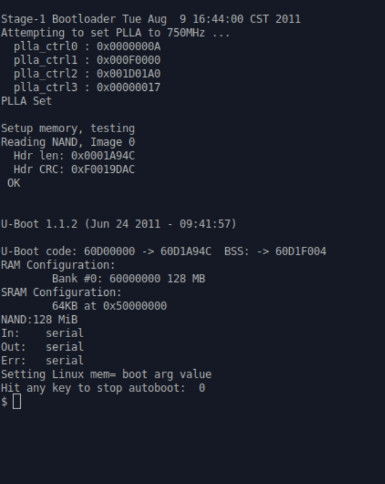
Once the Medion header is connected to your computer, it is time to try for the first time if everything works. I used the program ‘screen’ as a serial terminal with the serial connection available on /dev/ttyUSB0:
screen /dev/ttyUSB0 115200Connect the power supply to the mainboard and switch it on. Try to interrupt the bootloader by pressing a key during the boot. If everything works, you should see this on your screen:
Installation server
The installation of the NAS is only controlled through the serial interface to U-Boot. What is also required is a network connection to serve the boot image of OpenWrt during the first boot. For convenience, I used the same machine I controlled the boot from.
To serve the OpenWrt bootimage, a tftp server is required. I regularly use docker for my professional work, so that was the easiest way to run a tftp server on my machine without installing new software – convenient. The only extra thing needed then was to download the OpenWrt images for booting the first time.
I downloaded them from here, and selecting the images:
- openwrt-19.07.4-oxnas-ox820-mitrastar_stg-212-squashfs-ubinized.bin
- openwrt-19.07.4-oxnas-ox820-mitrastar_stg-212-initramfs-uImage
- openwrt-19.07.4-oxnas-ox820-mitrastar_stg-212-squashfs-sysupgrade.tar
However, this information might be outdated when you read this. Double check on the OpenWrt wiki page if this still is the current version. Also, I am not sure if all of these need to be served by the TFTP-server. Only the “openwrt-19.07.4-oxnas-ox820-mitrastar_stg-212-initramfs-uImage” seemed to be required immediately. Whatever.
Make a copy of the “openwrt-19.07.4-oxnas-ox820-mitrastar_stg-212-initramfs-uImage” file and rename it to “initramfs”. Then, to start the TFTP server, I used the pghalliday/tftp server docker image. I started the TFTP server using this command from the directory where I downloaded the images:
docker run -it -p 0.0.0.0:69:69/udp -v $PWD:/var/tftpboot:ro pghalliday/tftpPower down the NAS again (if is still is on) and connect it to the same network that your installation server is on. Note down the IP address of the installation server you are running the TFTP server on. Make sure no firewalls are blocking access to the TFTP server and that there is at least one static IP address in your subnet that you can manually configure for the NAS.
In my case, the server IP was 192.168.0.10 and I knew that I could use 192.168.0.13 as a static IP for the NAS. I will use these values as example values in the following excerpts.
Installing OpenWrt
The hot-phase. In this part, I describe the actual installation procedure of OpenWrt and the initial configuration of OpenWrt. This will irrecoverably wipe the old installed Zyxel operating system of the NAS. In case you have data stored on the disk that was removed from the NAS you should, be able to access that data later (I was able to). I would opt for a separate backup if you can afford it, however.
Flashing OpenWrt
Start the NAS and interrupt the bootloader by pressing some key (like demonstrated during the test-boot for testing the serial connection). Make sure that the TFTP server is running and that the NAS is connected to the same network as the TFTP server. Now, honestly, enter a few magic commands into the bootloader. You can look them up in the U-Boot Manual, they seem pretty straightforward, but I do not know why certain parameters need to be set to the values they are set to. The commands to enter are:
# Set server address to load image from
> setenv serverip 192.168.0.10

# Set address of this device
> setenv ipaddr 192.168.0.13

# Load the image into memory
> tftp 64000000 initramfs

# Actually boot from the loaded memory address
> bootm 64000000
This will start OpenWrt the first time. Note that this will load OpenWrt from memory! Nothing has been flashed onto the device itself yet. This is a good moment to test if OpenWrt if you want to give it a test run. If you are happy continue with the flashing procedure.
Now that OpenWrt has booted we need to tell OpenWrt to use a given ip address of the subnet we use to configure the NAS server. Go to your serial console, you should see this prompt:
BusyBox v1.30.1 () built-in shell (ash)

  _______                     ________        __
 |       |.-----.-----.-----.|  |  |  |.----.|  |_
 |   -   ||  _  |  -__|     ||  |  |  ||   _||   _|
 |_______||   __|_____|__|__||________||__|  |____|
          |__| W I R E L E S S   F R E E D O M
 -----------------------------------------------------
 OpenWrt 19.07.4, r11208-ce6496d796
 -----------------------------------------------------
=== WARNING! =====================================
There is no root password defined on this device!
Use the "passwd" command to set up a new password
in order to prevent unauthorized SSH logins.
--------------------------------------------------
root@OpenWrt:/#
Login as prompted and configure the network with a static IP address as follows (substitute the correct IP addresses and subnet ranges you want to use):
# Configure network options
> uci set network.lan.proto=static
> uci set network.lan.ipaddr=192.168.0.13
> uci set network.lan.netmask=255.255.255.0
> uci commit
# Reinitialize network stack and services
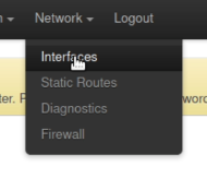
> service network restartNow you can switch to a webbrowser to connect to the OpenWrt web interface for the first time. Navigate to the running OpenWrt instance using the IP address you used above: http://192.168.0.13/ in my example.
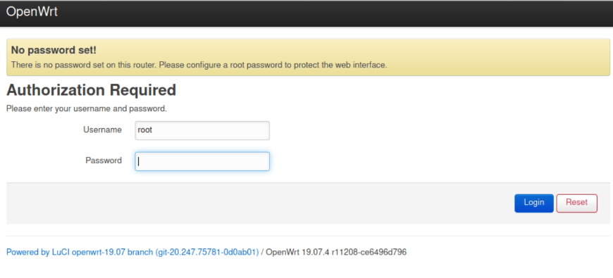
Login as root (with no password) as prompted. No need to set a password yet. This instance of OpenWrt will only ever run once! Navigate to the Backup/Flash-firmware area of OpenWrt via the System menu:
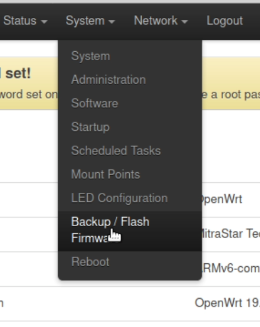
At the very bottom of the new page you will find a “Flash image…” button. Click it. Then select the file “openwrt-19.07.4-oxnas-ox820-mitrastar_stg-212-squashfs-sysupgrade.tar” that you previously downloaded.
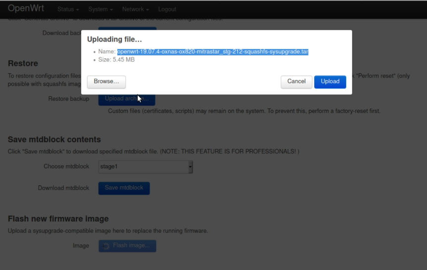
Press upload and you will be presented with the last option to turn around:
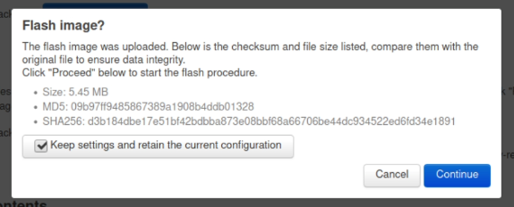
Pressing continue will start the flashing process where OpenWrt is written to the devices flash storage.
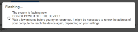
This step takes quite some time. In my case it took ~6 minutes. During this time the serial-console started to spit out a bunch of CRC-error messages. From all that I can tell this seems normal. Once the flashing was done, the device rebooted, however, it forgot its statically configured IP address. I therefore had to manually reconfigure that using the series of “uci set network*”-commands listed above.
Once you are able to connect to the web interface again, change the root-password! After that, you can check the network configuration one last time:
If they are correct, OpenWrt should have persisted the setting correctly so that they are restored after reboot from now on.
Reassembly
Congratulations, you now installed OpenWrt on the NAS. How to convert the device into a proper NAS again goes beyond the scope of this article. However, you will not need hardware access to the NAS anymore from now on. Everything can be configure through either ssh or the webinterface beyond this point.
This means that you can safely reassemble the NAS system now! Just follow the disassembly steps from above in reverse. The only tricky things with this step are to to fit the mainboard inside the metal housing again and for me the glue of the conductive tape deteriorated. I had to support them with a few ductape strips, which seemd to work fine.
Have fun with the new OpenWrt device!