Last year, I bought a Hobbist-“Robotic Arm” from Velleman. Even though there is a USB controlled version available as well, I though it might be a good chance to try to implement a USB controller myself, since I bought a few Arduino Micro boards last year as well. So putting both together and also powering the robot arm with an external power supply instead of a set of batteries seemed like nice two-week project.
Assembling
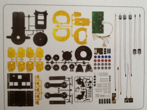
Injection molded robot arm pieces
The robot arm came as a set of injection molded plastic pieces which had to be pressed out of the injection molding frame. I did not take any pictures of that, but it was a relatively cumbersome process involving files and side cutters, being careful at every step not to damage the actual parts. The robot arm has 5 degrees of freedom and therefore comes with five simple DC motors. The motors have a filter capacitor strapped over their input leads, but that is all for the electric components that are included in the package. In the non-USB version the motors are directly connected to a battery compartment via a “remote control” which is just a collection of mechanical switches connected to the robot arm with a cable.
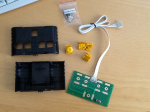
“Remote Control” for the Velleman robot arm
As you see to the right, I did not even bother putting the remote control together. Another thing that would lead to confusion later is that I was not able to figure out what voltage the motors did run on. I assumed that they would run on 5V-6V because the battery was taking 4x 1.5V A-cells but as it turned out later that was wrong.
After assembling, the robot looked like this:
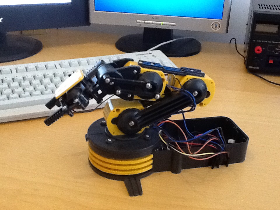
I did not put in the battery cover on because I wanted to connect my Arduino instead.
Controller design
I assembled the first prototype for the controller on a bread board. It was only able to control a single motor with a few MOSFET-transistors. However, for being able to make a proper controller board, I quickly ordered a few L293D driver chips from Amazon.
Counterfeit Chips
Ordering the L293D chips was a quite interesting experience in itself: I ordered the chips from Amazon and just added them to a basket with some other things, but did not notice the shipping time of 3 weeks! After comparing the prices between the ordered chips and the listings on Farnell, and also noticing that the chips I ordered were shipped from China, I was really sure that I ordered counterfeit chips. I heard a lot about this being a big problem in electronics – at least when buying components for commercial products – but seemingly it is really easy to buy weird components on the internet. Anyway, I tested the chips after they arrived and they seem to work. Perhaps not the greatest quality, but the chips are good enough for a little hobby project like this.
Breadboard design
I wanted to use an Arduino Micro board as control circuit for the robot arm. I
To accommodate it, made a breadboard design of the final controller board with LibreCAD. The final CAD file looks like this:
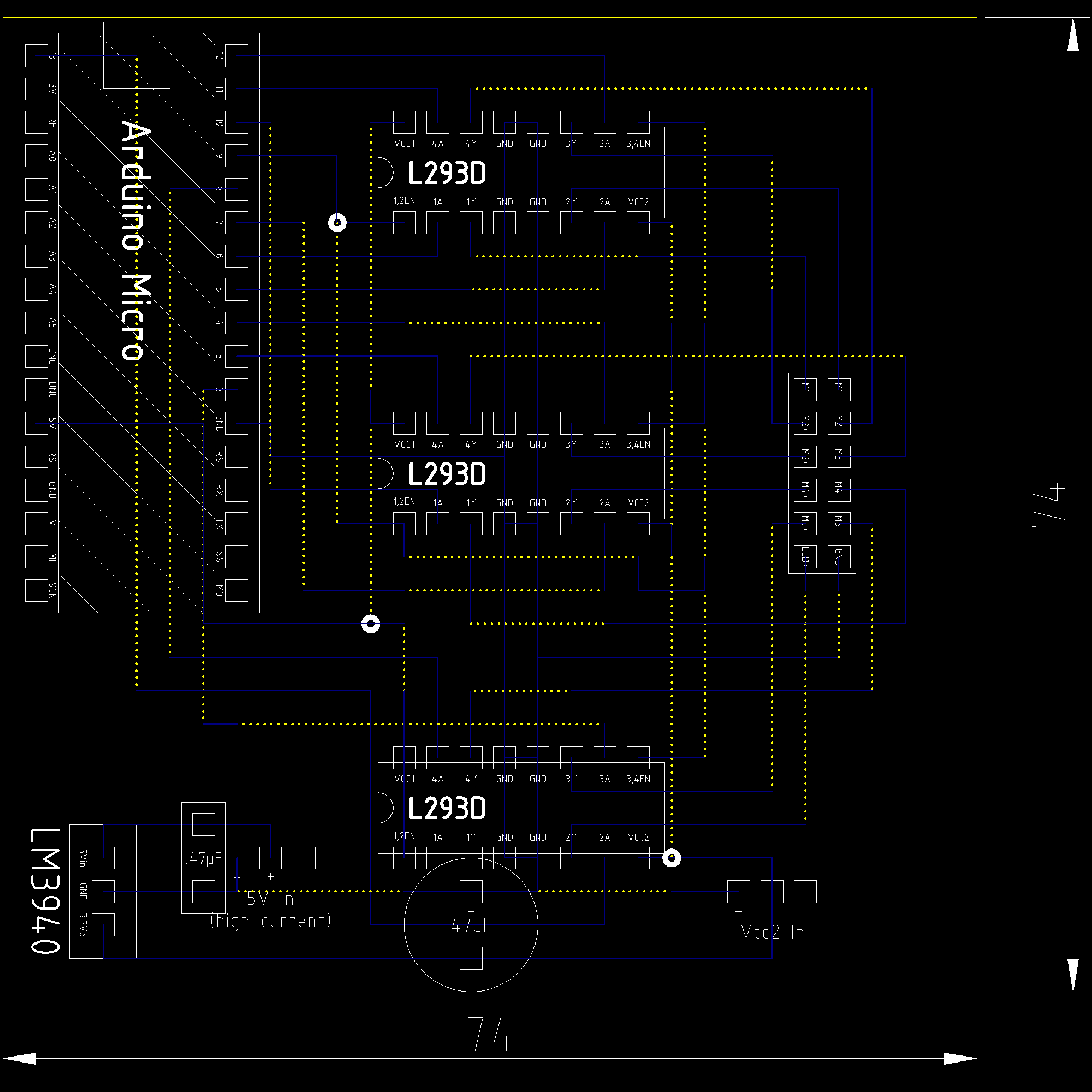
Low-resolution version of the Robot Arm Controller circuit board (click to open full-resolution).
The grid of the CAD file is aligned to a standard 2.54mm hole-grid, the width and height tuned so that the whole board would fit into the battery compartment of the robot arm. Stippled yellow lines are tracks that run on the upper side of the circuit board, blue continuous lines on the underside. The bottom left corner was designed after a first test run when I discovered that the motors did not run on 5V DC, but on 3V DC instead. I first planned to supply the motors with power through the header labeled “Vcc2 In” using an USB power supply. However, after discovering that I overdrove the motors with 5V, I added an LM3940 (bottom left) which reduces the input voltage to 3.3V. Choosing a linear regulator for this task is not quite optimal because of the high current draw from the motors, but as a starting electronics hobbyist I did not have any spare switch mode controller chips lying around. Also the remaining space on the board might have become insufficient to add a switch mode power supply with all its secondary components.
I borrowed the three-pin header design for the power connectors from model RC designs where the receivers are often powered with a similar setup. They are simple male SIP-connector posts. This also had the advantage that I could power the motors with a battery pack that I borrowed from a remote controllable boat so that the whole design became mobile when controlled with a laptop.
Issues
The board works. However, there are some concerning observations that I made while testing it: While the motors are powered through an external USB power supply, the main logic is still driven by USB-power. This was done by design to isolate the logic board from voltage/current spikes feeding back from the motors through magnetic induction. However, I discovered that some current leaks from the Arduino to the motors through the L293D chips. I find this a bit concerning because current might also feedback backwards through the L293D chips then and damage the Arduino. Given the data sheets of the L293D, the rails should be clamped with diodes to Ground and Vcc, but since I do not completely trust the origin of the used chips, this is still little bit worrying.
Another issue seems to be that the linear power supply does not manage to deliver a stable current. Especially when starting a motor under high load, it sometimes happens that it gets stuck because the supply voltage drops too much. This probably could be counteracted by using a (much!) bigger filter capacitor than the 47µF capacitor at the bottom of the board, or by redesigning the power supply circuit – again (switchmode?).
Last – a minor annoyance – but I calculated the width and height of the board correctly to fit into the battery compartment, but forgot about the depth! In the end, the Arduino, which is fit on top of the board using female SIP-connectors is sticking out way too high on the top so that the battery compartment cannot be closed. And even if it would fit into the battery compartment, the data cable and the 5V power cable for the motors would still have to come out of the back of the battery block somehow…
Verdict: Success – with lessons learned!